The early model C5 Corvettes (97-2000) were some of the first cars from GM to feature the LS engine, and that engine specifically was the LS1. GM obviously got a ton right with that engine as it has had a very long run and is by far the most common engine to swap into any other platform out there. However, there were some growing pains along the way for the LS1 engine.
One area of difficult for the LS1 was the PCV system. Most specifically, the car pulled air from a valve cover, which lead to oil intrusion into the intake, especially during heavy corner. Many folks will utilize a catch can to try and help minimize the effects of this, but then under high RPM applications you'll actually pull a lot of oil out of the engine, which is where it actually belongs.
In 2001 the LS6 was released to go in the C5 Z06 Corvette. This engine featured a slew of revisions, but the revision we're concerned with is the PCV System, and most specifically the updated Vally Cover.
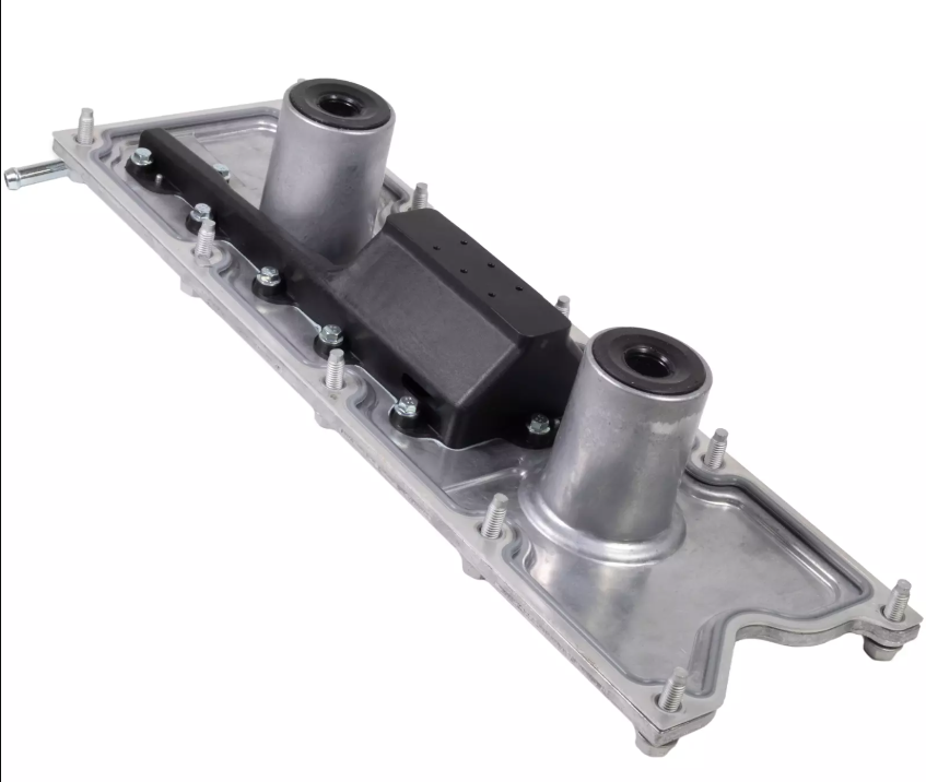
The updated Valley cover was now the location where the intake/PCV system would pull vacuum from. It featured a baffled intake, and with this newly revised location it vastly reduced oil ingestion into the PCV system during high load events. For folks updating their heads and cam, there really isn't any reason to not do this modification while they're in the area. Below is our article on just what you'll need to do the job.
Parts List:
- LS6 Valley Cover
- Steam Port Crossover Gaskets
- New Steam Port Crossover
- Full Crossover (Recommended, see our custom article)
- Plugs + Front (Streetable)
- Rear Crossover and front crossover (No idea)
- Likely to need parts
- PCV components
- Valve Cover PCV plug (If you're going to a true LS6 Style PCV system)
- Elite Engineer Catch Can (Recommended, though you can do custom for MUCH less)
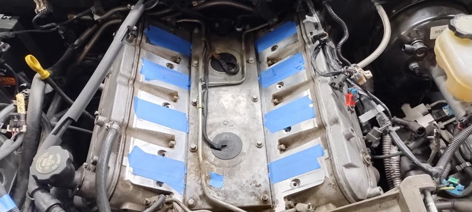
First of, you're going to need to remove everything to get to the Valley Cover. This includes the intake manifold and a variety of other plugs. At that point you'll also need to disconnect the knock sensors, which can be done by squeezing the plug with some pliers gently. Unfortunately, these plugs are generally brittle and thus break. The good news is a whole new harness for them is easy to acquire and we've linked them above. Then remove the knock sensors with a 22mm socket, followed by removing the valley cover itself. It is also worth replacing these knock sensors, as by most accounts they don't survive a reinstallation and ar often over 20 years old.
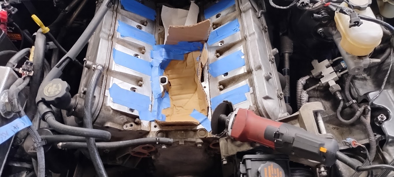
Now before you can put the new LS6 Valley cover on... you'll need to notch the block on the LS1 Engine. This can be harrowing, but don't worry, it's been done many a time. Start by blocking the areas above the cam, which are located at the front and rear of the enigne. With those thoroughly blocked off, tape off and shield the surrounding area. The block is aluminum, and cutting aluminum can be quite messy.
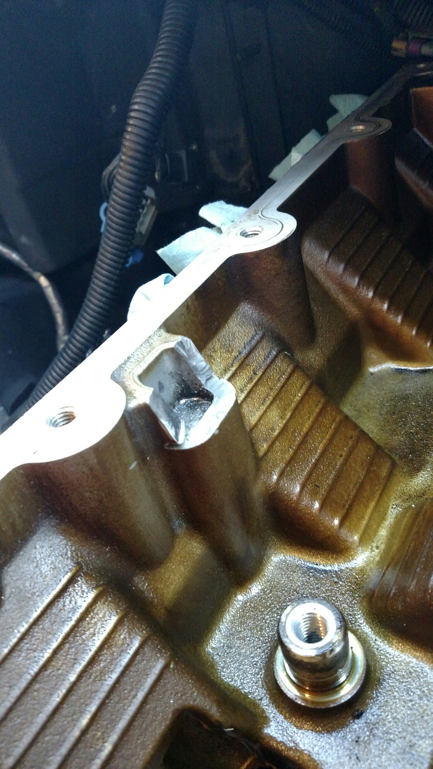
You'll want to measure approximately 3/4" below the lip, but honestly you can go as low that section has depth. Just don't exceed it if at all possible. You can use a Dremel or any other such sort of cutoff wheel, but do be aware the Aluminum likes to clog cutoff wheels. For a little hack here, get some wax (candle, ski/snowboard, etc etc) and run the cutoff wheel into the wax every second or so of cutting. The cutoff wheel will cut significantly more accurately.
if you used a dremel do consider using a small stone attachment or equivalent to smoothen the entire area out and make sure that there's no debris remaining to come free later. Last thing you want is any excess metal getting out. Speaking of, with the notch complete, clean the area out THOROUGHLY! Test fit the new Valley cover, and notch further if necessary. Perform one final cleaning with an oily rag (most likely to pick up metal debris) and then unblock the front and rear areas above the cam.
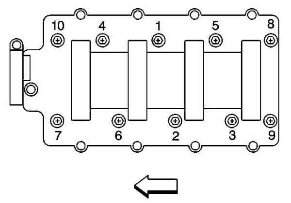
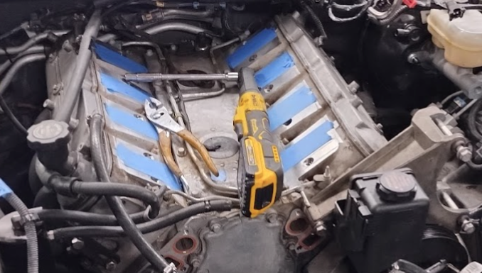
With the section you need notched and the LS6 Valley cover installed, next up is tightening it. All of the bolts will be torqued to a fairly mild 18 ft/lbs (See torque values), ideally utilizing the pattern above. While following this pattern is not as critical as it is on say, the heads, failing to do so can lead to mild oil leaks, so it's best followed.
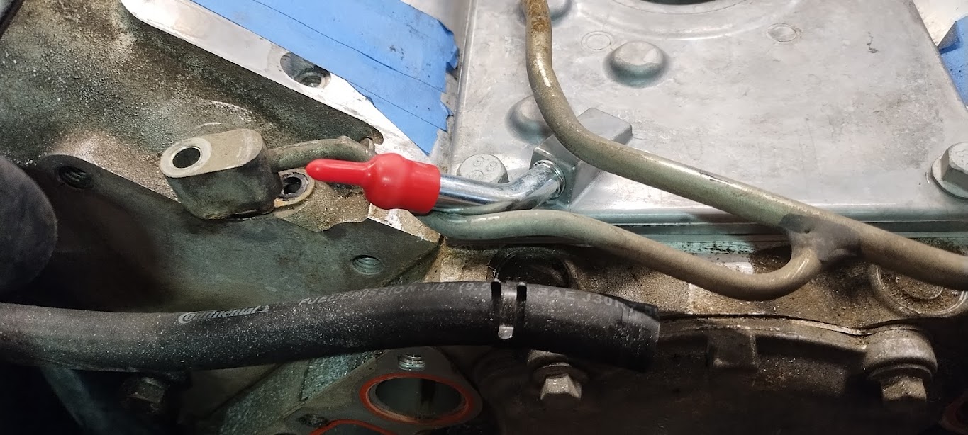
With the LS6 Valley Cover now installed, the next detail to navigate is your coolant crossover tubing. The OEM LS1 setup is ideal for a lot of situations, and can even be utilized with the LS6 intake if you trim the ribs beneath the intake. Unfortunately... the crossover tubing simply won't work with the LS6 intake.
You've got a few options here:
- Block the rear ports, and add a crossover tube up front.
- Get an aftermarket crossover tube setup of some sort.
- Do your own DIY Crossover setup.
Blocking the rear ports and adding a crossover tube supposedly has been associated with Cylinder 8 failures, so we don't recommend it. Getting an aftermarket crossover tube setup of some kind is highly advised. There's a variety of options out there on the market, just be sure whatever you go with is noted as being compatible with an LS6 Intake, and do be aware of the complexity of installing such a setup with the intake manifold, as generally most aftermarket setups will go over the intake manifold, very few to none go under the intake manifold.
PCV System Routing with the LS6 Valley Cover
The LS6 factory PCV system routing simply goes from the valley cover into the intake infold behind the throttle body, while the fresh air goes from the throttle body connection (which is actually pre throttle body) into the passenger valve cover. You will cap off the rear of the passenger valve cover, along with put a plug (linked in parts list) into the drivers side valve cover.
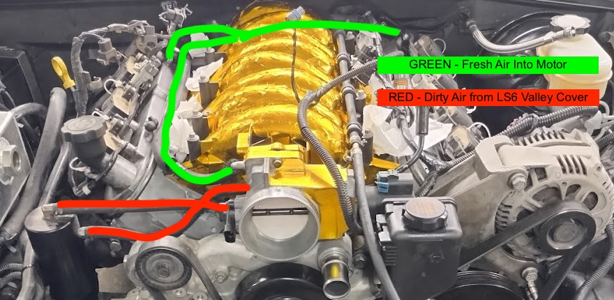
Now, while this is good enough for Chevy... there is some debate as to whether this is indeed the best. We generally go with a slightly different configuration that we've had great success with and is pictured above. You will retain the OEM LS1 PCV system hoses that connect to the back of both valve covers. However, you will remove the PCV valve in that system so it is free flowing. The PCV valve is now built into the LS6 valley cover. Now, instead of pulling dirty air from the back of the cylinder, you will insted utilize those hoses to allow fresh air to enter there. Dirty air will be pulled from the LS6 Valley Cover, ideally into an oil catch can if you have one to help ensure no oil is ingested into the intake, and then onwards into the intake manifold.
Why do we recommend this? Well the theory is fresh air can enter both sides of the motor, get pulled down through the crank case, up through the valley and out via the LS6 valley cover baffling and PCV. It's not just air that needs to move in this system though, oil drains down through the heads back into the crank case. Think of it like a vent in a plumbing drain system: Fluid wants to go down the pipe in your hose, but if there's nowhere for the air to go... the water will back up as the air can't be reasonably displaced. We theorize this is why some folks complain about having a ton of oil trapped in their heads. They went with a simple LS6 style system, or worse... they deleted the PCV system entirely and just vented one side to atmosphere.
Do we have ANYTHING backing up these claims? No, not really. At this point it's all conjecture and a collation of different folks efforts relative to their results. Still, this is our recommendation, it has not had any negative implications for us, and it does seem to yield the least amount of oil into our catch can.